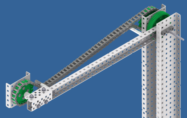
The chain lift acts in the same manner as a 4-bar linkage or a 6-bar linkage in that whatever is attached to it will maintain the same orientation throughout the movement of the arm.
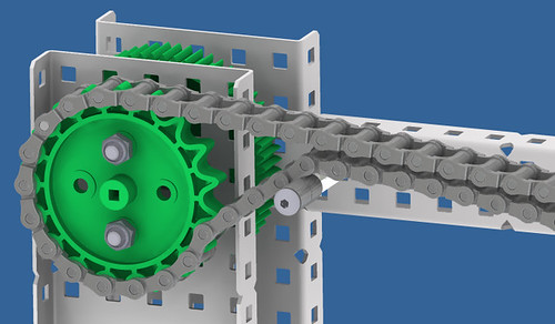
Typically chain lifts consist of two bars affixed to driven gears and two high strength sprockets that are able to be mounted i.e. 18, 24 or 30 tooth sprockets. The sprockets are mounted on either the inside or the outside of the bar and then to the tower, a chain is then wrapped around them forming a loop. The chain and tension it puts on the sprocket as the bar moves causes the sprocket that is bolted to the intake and thus the intake, to move. The sprocket on the intake moves relative to the sprocket on the tower ultimately maintaining the orientation of the intake.
There are a few ways to build this style of lift one way, with the sprocket inside the arms is as follows:
Note: With this style you will likely want the towers to be as far apart as possible.
• Build towers and fix a bar onto a gear as you would with a 4-bar linkage (you can also use a sprocket instead of a gear).
• Attach a sprocket to the inside of the tower on the pivot point but do not insert the axle into the sprocket else damage will be done.
• At the pivot point on the intake, bolt a sprocket to the intake then run an axle through this sprocket to the pivot on the arm.
• You might want to add some more support for the axle addition to the delrin bearing block on the arm’s pivot point; how this is done will likely depend on the spacing (e.g. another delrin on stand-offs bolted to the arm, a delrin on angle/L channel, a bracket or another method)
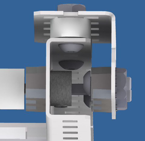
• Space the sprocket on the intake out so that the sprockets line up with each other
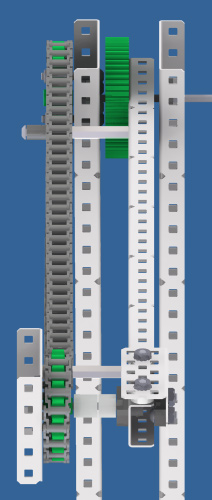
• Place tensioners as close as possible to the sprocket either end of the bar.
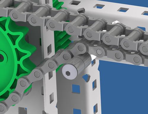
• Orientate the intake as desired then wrap the chain around and link it together. Ensure that at the intake end the chain goes under the tensioners and that it goes over at the tower end so that maximum contact with the sprocket is maintained
Some possible tips:
Chain is prone to slipping; when this happens the entire intake will tip forward or backward. Tensioners (usually spacers and/or stand-offs or even a bolt through the arm) positioned in the right place can ensure the chain has a large contact surface with the sprocket throughout the lift and will prevent slippage.
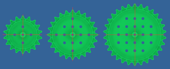
If you find you still have slack in the chain and cannot take out anymore links, check the tension above and below the sprocket, if they are vastly different trying moving the whole chain around by one link, if they are still roughly the same after that and you are using 18 or 30 tooth sprockets, try turning one sprocket (either at the intake end or at the tower end) by 90 degrees. This method works in taking up some of the slack because these two sprockets do not have the rotational symmetry like the 24 tooth sprocket: if directly above the bolt is a tooth, turn the sprocket 90 degrees and there will be no tooth (see the red lines in the image)
The chain can often snap for various reasons. Teams have found that because only some of the chain moves around the sprocket, it is possible to cable tie links together. Another idea might be to build a guard around the chain (if doing this out of polycarbonate, be aware of the limit allowed on competition robots).
Seeing as there are different sizes of sprockets that can be bolted onto metal, one can create a lift that will cause the intake’s orientation to change throughout the lift essentially simulating the lengthening and/or movement of bars in a 4-bar linkage.
One of our robots, Matlab, used a variation on the chain lift to reach 30″ – See photos and videos at https://www.aura.org.nz/archives/955
Good luck designing and building! If you have any questions, feel free to ask us on forums or e-mail [email protected]
[photoxhibit=19]